Optimizing RF PCB and FR4 Hybrid Lamination for Superior Performance
Introduction
In high-frequency application scenarios like 5G communication, automotive radar, and satellite navigation, where circuit boards must operate reliably at various frequencies, engineers consistently face a dilemma: pure high-frequency RF PCBs (printed circuit boards) meet signal transmission demands but cost 3-5 times more than FR-4; pure FR-4 PCBs are economical but suffer from severe signal loss above the 1GHz frequency band. Hybrid lamination technology, where different materials are combined in the PCB stack-up, is the key to solving this predicament – it’s like “layered dressing” for the PCB, using “high-end fabric” (high-frequency substrate) in critical locations for performance, and “basic fabric” (FR-4) in non-critical areas to control costs. This article will provide a comprehensive analysis of this core solution for high-frequency circuit board design, covering technical principles, design essentials, practical case studies, and the benefits of hybrid lamination for optimizing performance and cost.
Why Hybrid Lamination? The "Performance-Cost" Balancing Act in High-Frequency Design
Inherent Drawbacks of Pure Material Solutions
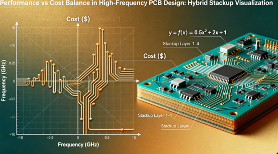
Pure RF PCBs (e.g., Rogers series) can have a dielectric loss (Df) as low as 0.0015 (10GHz), effectively reducing high-frequency signal attenuation, but the cost per square meter often exceeds 2000 RMB, creating significant cost pressure for large-area PCB boards. In contrast, pure FR-4 PCBs typically have a Df value between 0.02-0.03; when the frequency exceeds 5GHz, signal loss can reach up to 3dB per 10cm of transmission, completely failing to meet RF module requirements.
More critically, modern electronic devices are often hybrid systems of “high-frequency signals + low-frequency control”: 5G base station antennas require high-frequency materials to transmit RF signals, but their power management sections can sufficiently use FR-4; the RF front-end of automotive millimeter-wave radar requires PTFE substrate, while the data processing unit can perfectly use FR-4. This demand for “localized high performance” makes hybrid lamination technology an inevitable choice to meet specific design requirements such as signal integrity, thermal management and power distribution.
The Core Value of Hybrid Lamination Technology
Hybrid lamination technology achieves triple value through “precision material usage”:
·Cost Optimization: Using expensive RF substrates only in high-frequency signal layers can create significant cost savings, reducing overall cost by 40%-60% compared to pure RF PCBs.
·Performance Assurance: Loss indicators in critical signal paths are on par with pure RF PCBs, meeting return loss requirements below -25dB.
·Process Compatibility: Most hybrid solutions can adapt to standard FR-4 production lines without large-scale equipment modification.
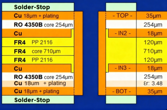
Measured data from a 5G base station manufacturer shows: After adopting the Rogers RO4350B + FR-4 hybrid solution, their antenna module cost reduced by 35%, while simultaneously passing reliability validation of 5 cycles of 288℃ thermal stress testing without delamination.
Fundamentals of Hybrid Technology: The "Golden Rules" of Material Selection
Core Material Property Comparison
RF PCB and FR-4 hybrid lamination is essentially the collaborative work of materials with different properties. Understanding the key parameter differences between the two is a prerequisite for design. When considering dielectric constant, it is important to select appropriate Dk values for each material to ensure optimal performance in hybrid stack-ups.
| Performance Parameter | Typical RF Substrate (Rogers RO4350B) | Standard FR-4 | Hybrid Design Requirement |
|---|---|---|---|
| Dielectric Constant (Dk) | 3.48±0.05 (10GHz) | 4.3±0.2 | Adjacent layer difference ≤ ±10% |
| Dielectric Loss (Df) | 0.0031 (10GHz) | 0.025 (10GHz) | High-frequency layer Df < 0.005 |
| Coefficient of Thermal Expansion (CTE) | 8.5 ppm/°C (X/Y axis) | 16 ppm/°C (X/Y axis) | Difference ≤ 5 ppm/°C |
| Glass Transition Temperature (Tg) | > 150°C | 130-180°C | Difference ≤ 30°C |
| Cost (Relative Value) | 5-8 | 1 | High-frequency layer proportion ≤ 30% |
Three Major Selection Strategies for Material Combinations
Zoning by Signal Type
·High-Frequency Signal Layers: Prioritize Rogers RO4000 series (hydrocarbon) or PTFE ceramic-filled substrates to meet 1-60GHz signal transmission needs, especially for RF and microwave PCBs where impedance control and material selection are critical.
·Power/Ground Layers: Use high Tg FR-4 (Tg ≥ 170°C) to enhance thermal stability and reduce costs.
·Control Signal Layers: Standard FR-4 is sufficient, no need for extra performance redundancy.
Local Hybrid Lamination Replaces Overall Coverage
Embed RF substrate modules only in areas where high-frequency components (like power amplifiers, antenna elements) are located, using FR-4 for all other areas. This solution can reduce RF material usage by over 70%, especially suitable for PCB designs integrating multiple modules, and offers the flexibility to produce a single board for prototyping or custom applications.
Gradual Transition to Reduce Characteristic Abrupt Changes
When the Dk difference exceeds 0.5, it is necessary to add a transition material (such as Rogers 2000 series prepreg) between the RF layer and the FR-4 layer, reducing signal reflection through a dielectric constant gradient and achieving consistent electrical properties across the stack-up.
Hybrid PCB Stackup Design Specifications
Reasonable stack up design is key to the success of hybrid boards, as it directly impacts electrical performance and manufacturing reliability. The following is a typical example of a high-frequency hybrid board stack up structure (using a 6-layer board as an example):
| Layer Level | Material Type | Function Description | Thickness Parameters | Key Design Points |
|---|---|---|---|---|
| Layer 1 (Top) | High-Freq Material (PTFE/Rogers) | RF Signal Layer | 0.25mm | 50Ω microstrip line, controlled impedance, impedance tolerance ±5% |
| Layer 2 | FR-4 | Ground Layer | 0.2mm | Solid ground plane, spacing to L1 ≤ 4mil |
| Layer 3 | FR-4 | Power Layer | 0.2mm | Adjacent to L2, spacing ≤ 3mil |
| Layer 4 | FR-4 | Digital Signal Layer | 0.2mm | Low-speed signal routing |
| Layer 5 | FR-4 | Ground Layer | 0.2mm | Bonded with L6 high-frequency material |
| Layer 6 (Bottom) | High-Freq Material (PTFE/Rogers) | RF Signal Layer | 0.25mm | Symmetrical design to prevent warping |
When designing the stack up, special attention should be given to plated through holes and plated vias to ensure reliable interconnections and consistent electrical performance. Optimizing electrical performance through careful stack up design is essential, and following precise processes in stack up construction will help achieve the desired quality and reliability.
4-Layer Basic Hybrid Structure (1-6GHz Applications)
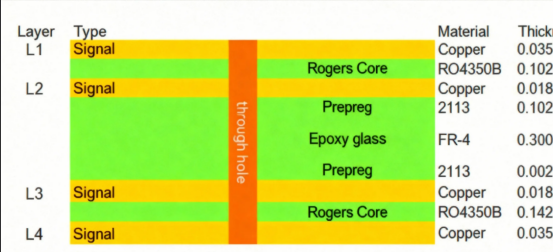
This structure is widely used in 5G CPE devices. The top RF layer ensures low-loss transmission of radio frequency signals, with its functionality focused on optimizing electrical performance and minimizing signal loss. The inner FR-4 layers handle power distribution and ground shielding, reducing cost by 52% compared to a pure RF 4-layer board.
6-Layer Local Hybrid Structure (Millimeter-Wave Applications)
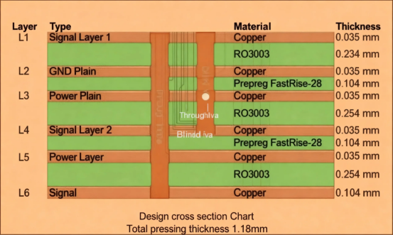
This symmetrical structure cancels out warping stress caused by CTE differences by symmetrically arranging the RF layers. It has passed temperature cycle testing from -40°C to 125°C in automotive millimeter-wave radar applications, and its balanced design also improves component assembly reliability.
Four Key Principles of Stackup Design
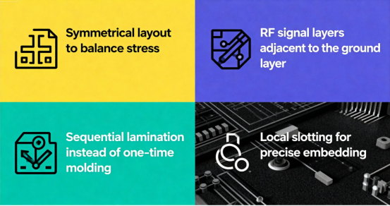
Symmetrical Layout to Balance Stress
Warping in hybrid PCBs mainly stems from Z-axis stress generated by CTE differences. Using a symmetrical structure like "FR-4 / RF Material / FR-4" allows stresses to cancel each other out, controlling warpage within 0.75%.
RF Signal Layer Adjacent to Ground Layer
Follow the “Signal-Ground” adjacency principle. The spacing between the ground layer and the RF signal layer should be controlled between 3-10mil, ensuring both stable impedance (50Ω ±10%) and shielding against electromagnetic interference from adjacent layers, as well as reducing noise.
Sequential Lamination Replaces Single-Stage Lamination
Independently laminate the RF sub-board and FR-4 main board first, then bond them together through secondary lamination. This process avoids delamination issues caused by different materials having different lamination profiles, especially suitable for PTFE and FR-4 hybrid.
Local Routing and Precise Embedding
Mill slots on the FR-4 main board (tolerance ≤ ±0.05mm), embed the pre-formed RF sub-board, and then laminate. This method can increase RF material utilization to over 90% and is the preferred solution for satellite communication PCBs, where precise pad design is also critical to ensure reliable embedding and optimal performance.
Process Breakthrough: Solving the 3 Major Challenges of Hybrid Production
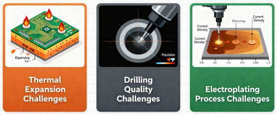
Thermal Expansion Mismatch Solution
The CTE difference between FR-4 and RF materials is the main cause of delamination, controllable through three methods:
·Select high Tg FR-4 (e.g., Isola 370HR, CTE=13ppm/°C) to minimize the difference with RF materials.
·Use low-flow prepreg (e.g., MEGTRON 6 PP) at the bonding interface to fill interlayer gaps.
·Adopt a stepped heating curve, raising the lamination temperature gradually from 160°C to 190°C to reduce stress accumulation.
Data from a PCB factory shows that after implementing the above scheme, the delamination rate of hybrid boards dropped from 12% to 0.8%, achieving high reliability in hybrid boards.
Drilling Quality Control Techniques
RF materials (especially PTFE) are softer than FR-4, prone to hole wall fuzzing, uneven surface formation, and size deviation during drilling. Solutions include:
·Using tungsten carbide drill bits with a point angle set to 130° (118° is used for standard FR-4).
·Optimizing drilling parameters: feed rate 50mm/min, spindle speed 30000rpm, replace drill bit every 50 holes.
·Applying plasma treatment (helium environment) to the PTFE layer to enhance hole wall adhesion.
Plating Process Adaptation Methods
The two materials have different hole wall treatment needs, requiring a segmented process:
·First treat the FR-4 layer with CF4-N2-O2 gas plasma to remove resin residue.
·Then treat the RF layer with helium plasma to improve hole wall wettability.
·Adopt electroless copper deposition + electroplating thickening process, controlling copper thickness to 20-25μm.
Industry Cases: Practical Applications of Hybrid Technology
5G Base Station Antenna Module
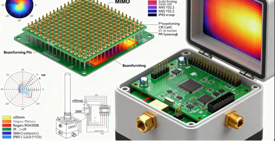
·Material Combination: Rogers RO4350B (top RF layer) + High Tg FR-4 (inner layers)
·Design Points: Used sequential lamination process; added transition PP between RF and FR-4 layers for a dielectric constant gradient from 3.48 to 4.3.
·Performance Data: Insertion loss < 0.3dB/in at 10GHz, return loss < -28dB, cost reduced by 45% compared to pure RF solution.
77GHz Automotive Radar
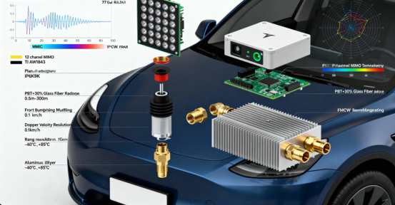
·Material Combination: PTFE ceramic-filled substrate (signal layer) + Standard FR-4 (power/ground layers), a hybrid structure highly relevant for microwave PCBs used in automotive radar applications.
·Design Points: Local hybrid structure, embedding RF material only in the radar transceiver channel area, slot width tolerance controlled within ±0.03mm.
·Performance Data: Ranging accuracy ±0.1°, passed 5 cycles of lead-free reflow soldering test without delamination, mass production yield reached 98.2%.
Low Earth Orbit Satellite Phased Array Antenna
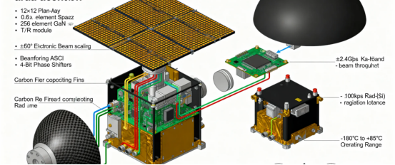
·Material Combination: Rogers RO3003 (radiating element layer) + FR-4 (feed network layer)
·Design Points: 3D local hybrid lamination, embedding a 6-layer RF sub-board into a 12-layer FR-4 main board, achieving high-density signal transmission. This hybrid lamination approach supports advanced RF designs by enabling precise layer management and material selection for optimal RF performance.
·Performance Data: Signal loss reduced by 40% at 20GHz band, weight reduced by 25%, meeting satellite lightweight requirements, and ensuring manufacturability for complex RF designs.
Pitfall Guide: 8 Common Mistakes in Hybrid Design
1.Arbitrary Material Combination: Directly laminating PTFE with standard FR-4 without considering CTE difference, leading to warping after soldering. To avoid this, you can request specific material combinations or custom options during the design or ordering process.
2.Neglecting Simulation Verification: Failing to simulate signal transmission with HFSS/CST, resulting in impedance mismatch in actual testing. Always perform simulation for verifying design concepts before production, and consider building proof-of-concept models to ensure your design works as intended.
3.Using Universal Lamination Parameters: Applying pure FR-4 lamination profiles, causing resin bleed-out on the RF layer.
4.Missing Transition Layer: Direct contact between RF layer and FR-4 layer, causing a 3dB increase in signal reflection due to Dk abrupt change.
5.Incorrect Drilling Parameters: Excessive drilling speed for the PTFE layer, resulting in hole wall roughness exceeding 1.5μm.
6.Wrong Copper Foil Type: Using standard electrolytic copper for the RF layer, increasing high-frequency loss by 20% (should use rolled copper).
7.Insufficient Precision in Local Hybrid Lamination: Slot position error > 0.1mm, leading to poor bonding between RF sub-board and main board.
8.Lack of Reliability Testing: Skipping thermal stress cycle tests, leading to interlayer cracking after batch use.
Summary: Future Trends of Hybrid Technology
With the proliferation of technologies like 5G millimeter-wave and satellite internet, RF PCB and FR-4 hybrid lamination will become the mainstream solution for high-frequency PCBs. Future development focuses on three areas:
·Material Innovation: Developing low-CTE FR-4 variants (e.g., CTE ≤ 12 ppm/°C) to reduce property differences with RF materials.
·Process Upgrade: Adopting Laser Direct Structuring (LDS) technology for precise manufacturing of RF regions.
·Intelligent Design: Using AI algorithms to automatically optimize stackup structure, balancing performance, cost, and manufacturability. A structured design process will be essential to ensure optimal results and manufacturability for complex hybrid stack-ups.
For engineers, mastering the core of hybrid technology is about “precise matching” – understanding both the characteristic boundaries of different materials and the performance requirements of the application scenario. Through scientific stackup design and process control, and by involving a PCB fabricator early in the project, every bit of cost is spent on the cutting edge of performance while minimizing manufacturing issues.
Author: Jack Wang