How to Choose the Right Printed Circuit Board Connector for Your Design
Printed circuit board (PCB) connectors are like the “bridges” that let different parts of your electronic design talk to each other. If you choose the wrong connector, your device might fail, break too soon, or cost more to fix. Picking the right connector is not hard if you know what to look for. In this article, I will show you how to choose the best PCB connector for your project, step by step. This will help you make your design work better, last longer, and be easier to build.
Core Principles for Choosing a PCB Connector
When choosing a PCB connector, you should not just pick the first one you find in a catalog. The right choice can make your product more reliable, easier to build, and cheaper in the long run. Here are three key principles that every engineer or designer should follow before making a decision.
1. Know Your Application
The very first step is to clearly understand where and how the connector will be used.
Consumer electronics like smartphones, laptops, and smartwatches usually need connectors that are very small, lightweight, and low-cost, because space is tight and price is a big factor.
Industrial equipment, on the other hand, often works in dusty factories or near heavy machines, so the connectors must be tough, resistant to vibration, and able to handle higher currents. Automotive connectors must work in harsh environments with extreme heat, cold, and constant vibration, and they must last for many years without failure because safety is critical.
Medical devices may require connectors that are waterproof, easy to clean, and highly reliable, as they are used near patients and cannot afford to fail. Knowing your application environment will help you quickly eliminate connectors that are not suitable.
2. Focus on Electrical and Mechanical Needs
After understanding the application, the next step is to look at the technical requirements.
Think about how much current the connector needs to carry and make sure it can handle it without overheating. If your design involves high-speed data, such as USB, HDMI, or RF signals, the connector must maintain good signal integrity to avoid data loss or interference.
You should also consider how many times the connector will be plugged in and unplugged. For example, connectors on a consumer device might only be used a few times, but connectors on test equipment could be used thousands of times, so they need higher durability.
Also, think about mechanical stress, like bending or pulling on wires, to make sure the connector will not break during normal use.
3. Balance Cost and Ease of Manufacturing
Finally, it is important to find a good balance between price and manufacturability.
Choosing the cheapest connector might save money at first, but it could lead to higher failure rates and expensive repairs later.
A connector that is slightly more expensive but has better quality can save a lot of time and money in production and after-sales service. You should also check if the connector can be easily assembled by automated machines, as this will lower labor costs and reduce mistakes during production.
Make sure the connector is easy to source from reliable suppliers so you will not face delays when you need more for future production.
Key Factors Affecting Connector Choice
Choosing the right PCB connector is one of the most important steps in designing a reliable electronic product. A connector that is too weak, too expensive, or hard to assemble can lead to failures, high costs, and unhappy customers. To avoid these problems, you need to carefully check several key factors before making your final choice.
1. Electrical Parameters
Electrical performance is the heart of connector selection.
Current Carrying Capacity:
Every connector has a limit for how much current it can safely handle. If you send too much current through a small connector, it will get hot, the plastic might melt, and the connection could fail. Always look at the datasheet for the current rating. If your circuit draws 3 amps, choose a connector that is rated for more than 3 amps to give yourself a safety margin. For power circuits, a thicker pin or terminal is usually better because it carries current more easily.
Signal Integrity:
For connectors that carry data — like USB, Ethernet, HDMI, or high-speed digital signals — signal quality is very important. Poor connectors can add noise or cause signal loss. Look for connectors that are designed for high-speed data and have controlled impedance. For example, differential pair connectors keep the two signal lines close together to reduce interference. This is especially important for designs that run at gigabit speeds or faster.
Voltage and Insulation:
Connectors must also be able to safely handle the working voltage. Low-voltage connectors might work for 5V or 12V circuits but could break down if used with 240V AC power. Good insulation between pins prevents accidental short circuits or sparks. If your design is for a high-voltage product, make sure to check the “creepage” and “clearance” distance between pins in the connector to avoid arcing.
2. Mechanical and Environmental Conditions
Connectors must survive the real-world conditions where your product will work.
Durability and Mating Cycles:
Some connectors are designed to be plugged and unplugged only a few times, while others are made to last thousands of cycles. For example, a connector inside a laptop that is never touched after assembly can be a low-cycle connector. But a connector on a test instrument that is connected every day must be rated for high mating cycles to avoid wear and loose contacts.
Shock and Vibration Resistance:
In products like cars, airplanes, or factory machines, connectors are often exposed to constant shaking and vibration. If the connector is not secure, it can slowly loosen and cause an intermittent failure. Look for locking mechanisms, latches, or screw-type connectors that stay firmly in place under vibration.
Temperature, Moisture, and Protection:
Connectors also face temperature extremes — from freezing cold to very hot. Some plastics become brittle in cold weather, while others soften in heat. If your product will be outside or near water, choose connectors with a good IP rating (such as IP67), meaning they are waterproof and dustproof. This is especially important for outdoor LED lighting, solar power systems, or medical devices where safety is critical.
3. Connector Types
Different jobs require different types of connectors.
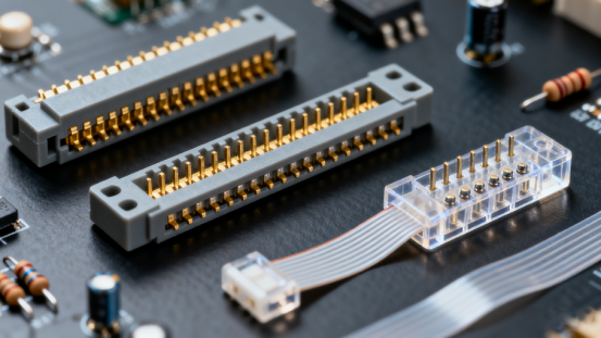
Board-to-Board Connectors:
These connect two printed circuit boards together. They are perfect for designs where space is limited, like small consumer gadgets, because they save wiring. Some are stackable to let you build multi-layer board assemblies.
Wire-to-Board Connectors:
These are used when you need to connect wires or cables to your PCB. They are common in power connections, motor control circuits, and battery packs. Some have crimp contacts for strong, reliable wire terminations.
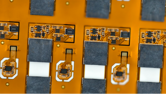
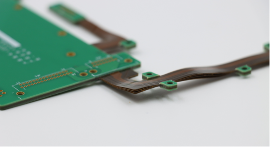
FPC/FFC Connectors:
Flat Flexible Cable (FFC) or Flexible Printed Circuit (FPC) connectors are often used in phones, tablets, and LCD displays. They allow very thin, flexible connections between boards and are great for products where space is tight and weight must be low.
High-Density or Custom Connectors:
If your design has many signals in a small area — for example, a server board or high-end medical equipment — you might need a high-density connector with many pins in a small footprint. Sometimes, engineers even work with manufacturers to create custom connectors that exactly fit their product needs.
4. Package Size and Layout
The connector must physically fit your design and your manufacturing process.
Space Fit:
Measure the available area on the PCB and inside the enclosure before choosing a connector. A connector that is too tall might prevent the case from closing, or one that is too wide might block other components.
Pin Pitch and Mounting Style:
Pin pitch is the distance between pins. A small pitch saves space but is harder to solder and more expensive to manufacture. Large pitch connectors are easier to work with but take more space. Also, decide if you need through-hole connectors (stronger, good for mechanical stress) or surface-mount connectors (better for automated assembly and compact design).
5. Manufacturability and Cost
Even the perfect connector is useless if you cannot build your product efficiently.
Ease of Assembly:
Choose connectors that can be easily placed and soldered by automated machines. This reduces errors, lowers labor costs, and improves quality consistency. Avoid connectors that require too much manual work unless your production volume is very small.
Cost and Supply Chain:
Finally, check that the connector is affordable and available from multiple suppliers. Relying on one hard-to-find connector can delay production if there is a shortage. Using a widely available connector keeps your supply chain flexible and your production running smoothly.
Step-by-Step Process for Choosing a PCB Connector
Choosing the right PCB connector is critical for building a reliable, cost-effective, and manufacturable product. Following a clear step-by-step process reduces mistakes and ensures the connector fits your design perfectly.
1. Define Your Design Needs
The first step is to clearly understand the requirements of your project. To do this, create two detailed lists: electrical requirements and mechanical requirements.
For electrical requirements, include the maximum current and voltage the connector will carry, and whether it will transmit power, data, or both. If your design includes high-speed signals, make sure the connector maintains signal integrity and minimizes interference. For example, a USB connector must transmit data without loss, while a battery connector must handle high current safely.
For mechanical requirements, consider how many times the connector will be plugged and unplugged, the physical stress it may face, and the environmental conditions, such as temperature, vibration, moisture, or dust. For instance, an automotive connector must handle constant vibration and high temperatures, whereas a connector inside a small indoor device may not need such durability. Writing these requirements down ensures you do not overlook any critical factors, and it provides a solid foundation for your next selection steps.
2. Do an Initial Selection of Connector Type
Once the requirements are clear, you can narrow down the connector family and decide on the mounting style.
Board-to-board connectors are ideal for connecting two PCBs directly, especially in compact designs where space is limited. Wire-to-board connectors work well when connecting wires or cables to a PCB, commonly used in power circuits or signal lines. FPC/FFC connectors are suitable for flat or flexible cables, often used in smartphones, displays, or other compact devices.
Next, consider the mounting style and physical size. Through-hole connectors are stronger and better for mechanical stress but occupy more PCB space, while surface-mount connectors save space and are compatible with automated assembly but may be less robust mechanically. By making these decisions early, you reduce the number of options and focus only on connectors suitable for your design environment.
3. Talk with Suppliers and Get Samples
After narrowing your options, the next step is to communicate with suppliers or manufacturers. Request datasheets to confirm the current, voltage, pin configuration, and environmental ratings of the connector. Ask about pricing, availability, and certifications such as UL, RoHS, or automotive standards.
Whenever possible, request physical samples for testing. Datasheets may not reveal practical issues, such as the ease of plugging and unplugging, tightness of fit, or solderability. Additionally, suppliers can provide advice about assembly, reliability, and potential pitfalls. Testing actual parts before production helps you identify issues early and avoid costly mistakes.
4. Build and Test a Prototype
Once you have samples, it is crucial to test them in a prototype PCB. Begin with electrical tests to ensure the connector handles the required current and voltage safely. If the design involves high-speed signals, verify that the signals remain clean and free from interference.
Next, test the mechanical durability. Plug and unplug the connector the expected number of times, and check whether it remains secure. If your device will be used in environments with vibration or shocks, simulate these conditions to ensure stability.
Finally, conduct environmental tests, such as temperature extremes or moisture exposure, especially for outdoor or industrial products. Prototype testing helps you catch potential problems before moving to mass production, which is much cheaper than correcting issues afterward.
5. Finalize and Move to Production
After successful testing, you can finalize your connector choice. Confirm the exact part number, supplier, and pricing. Update your PCB design files with the correct footprint, pinout, and mounting details.
It is also important to consider long-term supply. Make sure the connector will be available for future production runs, or identify alternative suppliers in case of shortages.
Finally, document handling instructions, soldering parameters, and any special assembly notes for manufacturing. Following this structured process ensures that your design will be reliable, production-ready, and easier to build.
Common Mistakes and How to Avoid Them
Choosing the wrong PCB connector can lead to serious problems, such as product failure, higher costs, and production delays. To make the right choice, it is important to understand the most common mistakes and how to avoid them.
1. Ignoring Environmental Conditions
A very common mistake is not considering the environment where the connector will operate. For instance, a connector designed for indoor consumer electronics may fail if it is exposed to heat, vibration, moisture, or dust in industrial or outdoor applications.
If environmental factors are ignored, the connector can loosen, corrode, or break over time, causing device failure.
Therefore, always check the temperature rating, vibration resistance, and protection level (such as IP ratings for water and dust) to ensure the connector is suitable for its intended environment.
2. Overdesigning or Using Excessively Robust Connectors
Another mistake is selecting a connector that is much stronger or more complex than needed. While it may seem safe to overdesign, this approach can increase costs, occupy extra PCB space, and complicate assembly.
For example, using a high-density industrial connector in a small consumer device adds unnecessary expense without improving reliability.
To avoid this, match the connector’s specifications to your actual needs, balancing durability, size, and cost. This ensures you do not overpay or make assembly more difficult than necessary.
3. Focusing Only on Price and Ignoring Quality
A third frequent error is choosing the cheapest connector without considering quality. Low-quality connectors may function initially but often fail after repeated use, environmental stress, or high-speed signal operation.
This can lead to customer complaints, warranty claims, or even product recalls.
Therefore, consider both price and quality. Select connectors from reputable suppliers, verify certifications (UL, RoHS, etc.), and test samples during prototyping to catch potential quality issues before mass production.
Conclusion
Choosing the right PCB connector is more than just picking a part from a catalog. The right connector can make your device work better, last longer, and avoid unexpected failures. It improves overall performance, ensures reliable operation, and makes your product easier to build and maintain.
To make the best choice, it is always a good idea to consult with professional PCB suppliers or connector manufacturers, such as PCB MASTER. They can provide technical advice, recommend the most suitable connectors for your design, and help you avoid common mistakes.
By carefully selecting connectors and seeking expert guidance when needed, you can ensure your electronic design is both reliable and cost-effective. Take the time to make the right choice, and your product will perform better from day one.
FAQs
1. How do I know if a connector will last for many years in my product?
To determine a connector’s lifespan, start by checking its mating cycle rating, which tells you how many times the connector can be plugged and unplugged without wearing out. For example, a connector rated for 500 cycles may be suitable for a device that is rarely disconnected, but a test instrument or automotive sensor might need one rated for 5,000 cycles or more.
Next, look at the materials used for both the pins and the housing. Gold-plated pins resist corrosion and maintain good electrical contact over time, while high-quality plastic housing can withstand heat, stress, and repeated plugging.
Finally, perform prototype testing under real conditions. Simulate the environment your product will face, such as vibration in a car, heat in industrial equipment, or occasional contact with moisture. Observing the connector’s performance in these tests is the most reliable way to predict long-term durability.
2. Can I use one type of connector for all my products?
Usually, one connector type cannot fit all product needs because different products face different electrical, mechanical, and environmental challenges.
For example, a small connector designed for an indoor consumer device may fail in an automotive or industrial environment. It might overheat under high current, become loose under vibration, or degrade quickly in extreme temperatures.
Therefore, you should select a connector based on the specific requirements of each product. Consider the current it will carry, the number of plug/unplug cycles, environmental conditions, and space constraints. While using the same connector for multiple products might save design effort and inventory management, it can cause reliability problems if the connector is not strong enough for harsher applications.
3. Why is it important to test connectors before mass production?
Testing connectors before production is essential because even if a connector looks suitable on paper, it might fail under real-world conditions.
Start by installing the connector in a prototype PCB. Check the electrical performance to ensure it handles the expected current and voltage. Test high-speed signals to verify that the data remains clean without interference.
Then, test the mechanical aspects. Plug and unplug the connector multiple times to ensure durability. Apply vibration or shock if the product will face such conditions.
Finally, simulate the environmental conditions your device will encounter, such as temperature changes, humidity, or dust. This step helps identify potential failures early, preventing costly recalls or redesigns after full production. Prototype testing ensures your product is reliable, safe, and ready for real-world use.